

COMPUTER WARGAME DESCRIPTION
Historical Software Corporation
SUMMARY
Battle Command is a hybrid between a commercial computer wargame and a professional training simulation. It offers the robust realism of a training simulation and the graphical appeal and playability of a commercial wargame. Players can create their own scenarios and launch multiplayer games with relative ease. Battle Command represents a new approach to distributed simulation design, and has a preceptual strong emphasis on functionality and usability, rather than theoretical or academic test-bedding. Ubiquitous fast internet and LAN, surplus CPU processing capacity, and robust 3D graphics capabilities make plausible a generational approach to distributed, user level simulation design for land warfare training.
1 Introduction
The Battle Command Tactical Warfare Simulation (BCTWS) offers a new approach to tactical level modern warfare gaming. Where BCTWS chiefly departs from previous offerings is in the utilization of robust and integral 3D graphics for the display of both terrain and entities, and as a first-order user interface. Also, a unique and powerful distributed simulation architecture is implemented that combines a dedicated multi-participant structure, centralized simulation control, frugal data transfers, the offloading of processing to connected clients where possible, and which leverages the features and capabilities of the target Windows operating system. As a result usability, immersion, and realism are increased, and implementation costs, user training, and complexity are decreased over several possible alternatives.
2 Distributed Simulation Architecture
The BCTWS distributed simulation architecture (see Figure 1) is built upon a centralized server program with a thirty-second simulation update interval (with various time-compression settings possible). Multiple client programs connect into the server via two TCP connections; one to receive simulation updates from the server and one to send orders and other information to be processed by the server. All parties must load the same set of scenario files locally, this dramatically saves on required network simulation update traffic as only changes between simulation updates are sent to the connected clients. The data sent from connected clients to the server in form of orders to units is minimal. If a connected client encounters an internet, network, or local computer problem, they can easily shut-down, restart, load the scenario files in play, and rejoin an ongoing situation.
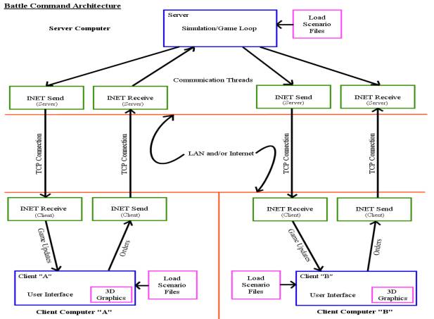
Figure 1: The Battle Command Architecture.
3 Terrain Modeling
Terrain is modeled in 100 meter grid-squares (GSs) and the values for each map grid-square are stored in a map database file. Each GS is coded for a base terrain value (e.g.: dirt, grass, sand, mud, gravel, etc.) and a terrain cover value (e.g.: building types, trees, forest, jungle, rocks, etc.). The terrain cover values also have a related terrain cover height and density value. Each of the four GS corners has a terrain elevation value stored in the map database file. Special software map utility tools have been created to make the job of encoding terrain for various map files easier. GS Elevation data is primarily derived from the NASA SRTM 90 data. SRTM 90 offers terrain elevation values spaced at a nominal 90 meters for most of the Earth. These values are easily interpolated into a 100 meter grid. To determine GS terrain values, the USGS offers Digital Orthographic Quads (DOQs) satellite photography at 1 meter resolution for the entire U.S., and lower resolutions for most of the rest of the Earth. By mapping satellite photography over a pre-determined 100m grid array, terrain for individual GSs can be determined and encoded. Using DOQs has an additional important advantage in that the source bitmap images can be reformatted as needed and used as programmatic textures and mapped over terrain wire frame meshes as visual images in the 3D map view. This is a critical advantage as attempting to create visually appealing terrain bitmaps for use over a height-mapped terrain mesh is not a trivial task.

Figure 2: A sample Battle Command map: the 50km x 50km area of the Ft. Irwin National Training Center.
The dimensions of 500×500 GSs required a quarter million terrain encodings.
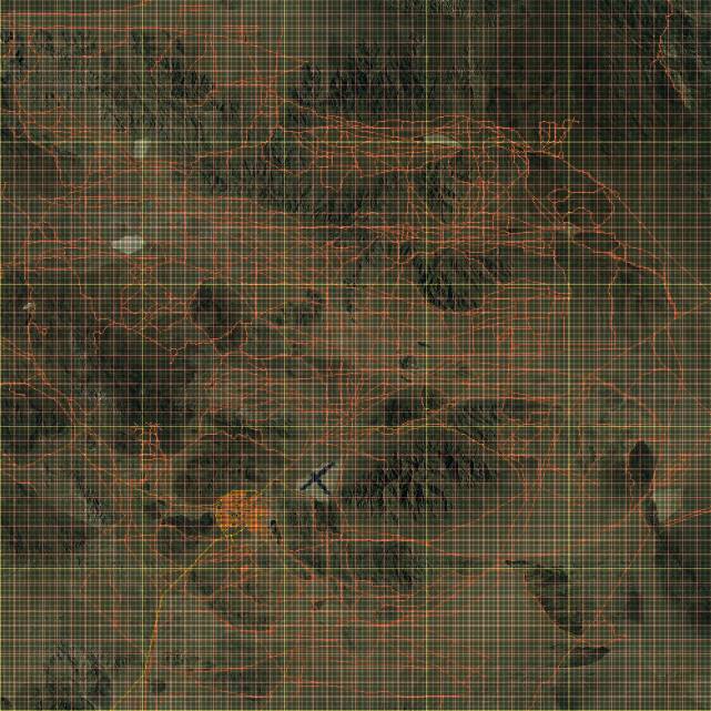
Figure 3: An example of terrain encoding using the 50km x 50km NTC map: the area road network GSs are shown in red.
4 3D Graphics

Figure 4: A view of Tiefort Mountain (having the highest elevation at the NTC) from the south.
The mock battles at the NTC are fought largely in relation to their location relative to major terrain features and landmarks.
The terrain largely dictates the prosecution of the battle.
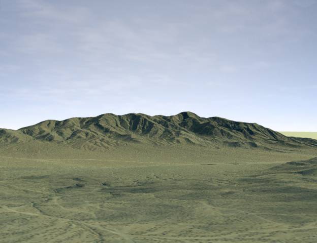
Figure 5: The same view using 3D graphics from a nearby location.
Participants quickly become familiar with terrain features and location by eye after several battles.
The basis of the participant interface in the BCTWS are the hardware-accelerated direct manipulation 3D graphics. Users can easily move and orient multiple camera viewports to any position and orientation over the battlefield. Copious options exist to customize this display, for example options exist to change the terrain height multiplier, show or hide place names, change unit counter scales and displays, and to show or hide weapon visual effects. Users can find terrain information such as type and elevation by moving the map crosshairs over portions of the map. To find information on and control units, a user clicks on a unit counter to bring up its control window. Multiple 3D map windows can be opened and configured independently. In general what the user sees in a 3D map display is the 100 meter interval map terrain mesh with elevations derived from the SRTM90 data, reformatted DOQ bitmaps superimposed over this mesh as “texture†files, a single color map border area that extends from the edge of the map to the horizon, a spherical “sky-dome†which is textured with a panoramic atmospheric photo to represent the sky., and finally cubical unit counters with superimposed text and image information—representing the location and state of various units under user, friendly, and enemy control (if spotted).
5 Sound
Several types if positional sounds are included into a stereo mix which is based on the source sounds 3D coordinates and orientation and the current location and orientation of the camera over a selected 3D map. The types of sounds included are: vehicle engine sounds, vehicle and troop movement sounds, improving position sounds, weapon firing sounds, and an ambient background sound. Doppler shift and realistic sound roll offs are incorporated into the stereo mix calculations. The result of this is that a sound field representative of what a participant would experience on the battlefield from their current location or perspective is created.
6 PARTICIPANT Interface
As in complex real world situations, participants must develop techniques for dealing with information overload. A glance at the orders tab from the unit information window (see Figure 6) emphasizes the fact that there is a tremendous amount of detail, options, and nuance to individual items in the simulation. However—a good rule of thumb would be 10% of the clutter is what is used 90% of the time. Therefore, if a participant can struggle through a learning curve where they become proficient with the 10% they need to effectively manage forces, they can find the remaining 90% when needed. The interface follows the recommended guideline that similar information is group together. As an example, the orders tab has unit settings for such items as:
1. Assault Orders
2. Engagement Ranges
3. Indirect Fire Instructions (and ammo to be used)
4. Load/Unload as cargo orders
5. Movement speed instructions
6. Resupply orders
By combining various combinations of orders simultaneously, the participant can coax units under control into complex behaviors. In general, unit orders follow a structured precedence scheme where, if set, certain order types will be acted on before orders also set that have a lower precedence. For example, a unit with active waypoints (for movement) will continue moving if an “improve position†order is also set. When stopped with no waypoints remaining, the unit will begin improving its position (by “digging-inâ€).
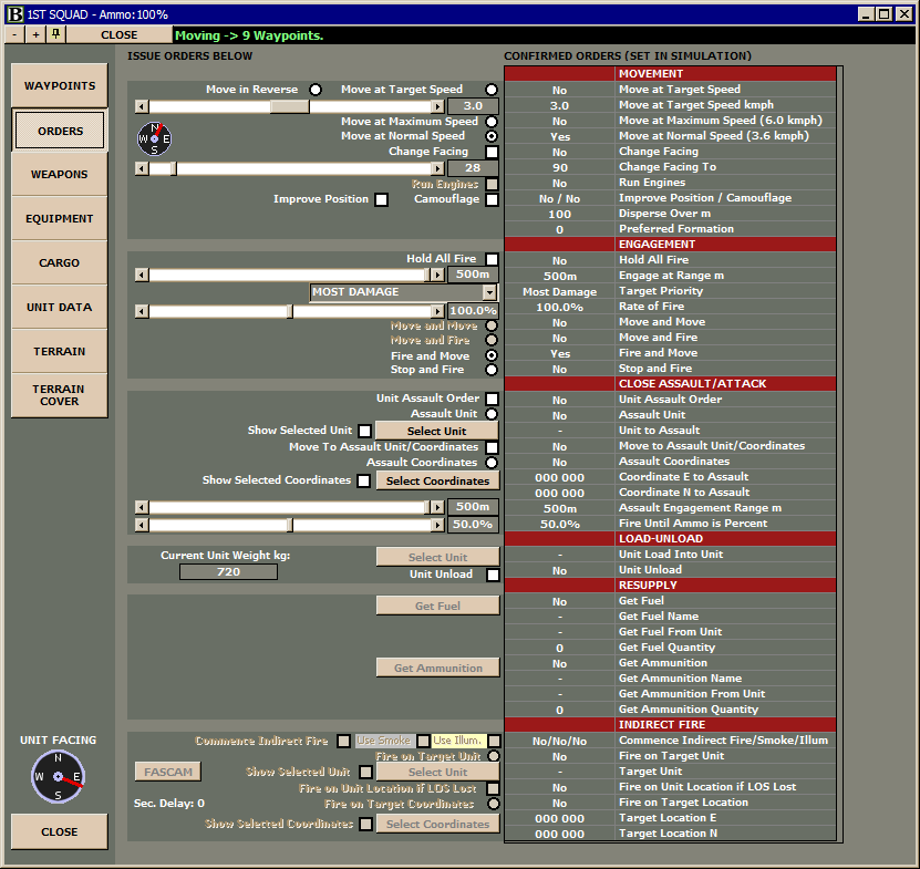

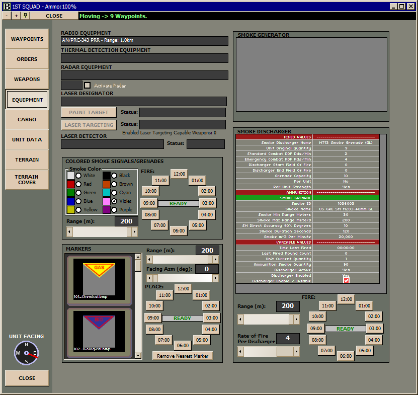
Figures 6A, B, and C: Unit Information window orders tab. Here a participant can issue orders and directives to units under their control.
7 Visual, IR, and Radar Lines-of-Sight
Visual lines-of-sight are traced between all friendly and all enemy units at each 30 second simulation update—and twice if the unit moved during the interval (once before and once after the movement). If an unobstructed visual line-of-sight can be traced, an enemy unit becomes “spotted†at a specific spot quality depending on its distance from the spotter and the current situation visibility level. Spot quality increases from: 1. spotted as an enemy unit, 2, spotted as a general type of unit, to 3. spotted as a specific type of unit. Other factors are also considered for spotting distances, such as the remaining strength of the unit. Baseline spotting distances for each unit are stored in that unit’s fixed information data. Ongoing values constantly change based on the environmental conditions and other values. An unobstructed visual line-of-sight is imparted if no terrain or terrain cover blockages exist between spotter and spotee. For spotting based on forward looking infrared (FLIR) or night vision devices (NVD), the calculation is similar however current situation visibility (based on day lighting and atmospheric visibility) is ignored and only the quality of the FLIR or NVD equipment is considered out to a maximum range. Radar spotting uses a fourth-power model based on radar cross sections. The model is fourth power in that a radar signal spreads as it moves away from the antenna, and the echo spreads again on its way from the contact back to the antenna, so there is a “fourth power†relationship between radar contact sizes and their detection range. Based on the technical capabilities of the radar (maximum range and m^2 radar cross section detectable at the maximum range), radar can detect various types of enemy units without regard to environmental conditions if there is a clear LOS to the contact. As an example, the JSTARS aircraft is modeled with a 250km maximum vehicular detection range in the simulation—a dramatic advantage to the side possessing this capability in a conflict.
8 Environmental Conditions
Several important environmental conditions are modeled as a result of their strong influence on land warfare. Sun position and the resulting daylight level, changing atmospheric visibility (saved as “waypoints†with the scenario file), ambient temperature, and wind direction and speed. Smoke and dust clouds move and rise with wind speed and direction and can be observed at their correct size, density, and location in three dimensions.
9 Movement
Movement over terrain takes into account several factors: the maximum movement speed of the unit over the terrain and the obstacle presented by any terrain cover in the GS, the ordered speed, the grade change present in the movement (there is a grade change ability limit for various units), fuel consumption due to the movement (based on cargo weight, grade change, speed, and terrain type), and random “vehicle stuck†events over extremely bad terrain.
10 Combat Results
Combat results build upon the basic model of probability of hits and probabilities of kills at various ranges. Benchmark values are modified by several factors. As little of the combat results methodology as possible is hard coded, much can be altered as needed in the unit and weapon database values by end users, and also in the program wide “fire results databases†where many multipliers can be changed to make certain types of fire more or less effective as needed or desired.
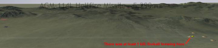
Figure 7: An Apache fires Hellfire ATGMs from 5,290m at a group of T-90S tanks. There is a visible semi-transparent arc shown over the trajectory of the missiles.
11 Aircraft
The primary advantage of using a 3D interface with aircraft is that icons or counters representing aircraft can be positioned at their actual scale altitude above the map. This advantage is extremely important in land warfare simulation, specifically for ground attack helicopters and aircraft. For example, ground attack helicopters typically follow “nap-of-earth†altitudes before doing a popup to spot and surprise enemy forces within sighting and weapon range. Perceiving aircraft at scale altitudes gives the participant intimate understanding of both the terrain in question (which must be exploited in order to do the most damage), and the current and planned behavior of the aircraft—when and exactly where to do the popup, and in estimating the potential vulnerability of the aircraft during the popup.
12 Automated Pathfinding
Intelligently moving entities about for long distances on a large terrain map is no trivial task for a participant, especially if they intend for vehicles to follow road networks or at least the most amenable terrain to their destination. BCTWS offers an extensive automated pathfinding facility built upon the powerful A* pathfinding algorithm, and with the addition of multiple goal cost analysis. Participants can select a destination for a unit, input from a menu of search goals (e.g.: fastest, usage of terrain cover, “straight-lineâ€, lowest elevation, highest elevation, and friendly/enemy proximity), and have the system compute the optimal waypoints and times to the destination. In several seconds and with a few mouse clicks a waypoint path may be created that contains 50-100 waypoints which would have taken many minutes to input by hand. Follow-on units (as in a convoy or formation) can elect to “follow†a lead unit to a destination and will automatically stop at incremental spans behind the leader.
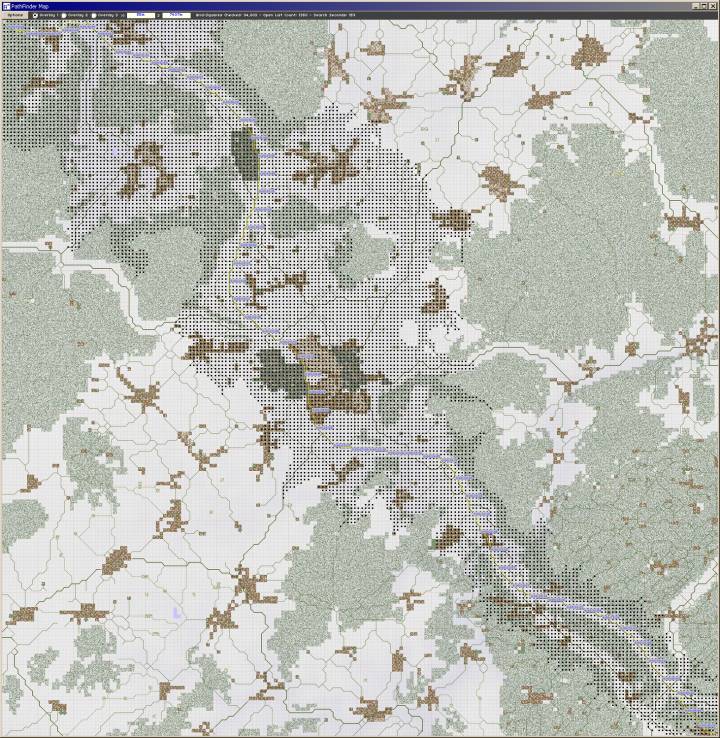
Figure 8: St. Vith Map (20km x 20km) Search Path – Starting in upper left and moving to lower right.
Since a major highway runs along the map from the upper left to the lower right, this search was aided by this fact.
94,003 nodes were searched, and the search took 159 seconds.
The vehicular unit would arrive at its destination in 42 minutes and 36 seconds after traveling mostly along highway.
13 Fuel and Ammunition Resupply
BCTWS tracks fuel and ammunition expenditure by fuel type quantity and ammunition round or item. As a result, each fuel and ammunition type is assigned an identification number and cargo-carrying entities may resupply both fuel and ammunition to receiving units. Receiving units can opt to transfer supply quantities to fuel tanks or appropriate weapon ready stowage, or to any available onboard cargo capacity themselves. Transfer times are based on available pump or labor capacity, and entities must remain in proximity for any transfer to continue.
14 PARTICIPANT Communication
Currently participants can communicate over multiple text chat channels through the client program that can be either game wide or side specific channels.
15 TEXT-TO-SPEECH (TTS)
There are numerous options to configure the Text-to-Speech (TTS) capabilities of the program. For example, TTS can verbally give friendly and enemy casualty and destroyed unit reports, units out of fuel and ammunition reports, and also read aloud text communications from other players. TTS simulates some of the verbal communication present for a commander with staff and during radio monitoring.
16 Example Scenario: “Team Abbeyâ€
Several introductory battle scenarios are included with the NTC map. These are intended to be small and quick battles that let participants familiarize themselves with the interface and simulation approach. In “Team Abbeyâ€, A US mechanized infantry platoon supported by two Apache helicopters must attrite an approaching OPFOR armor force.

Figure 9: Team Abbey US Situation.
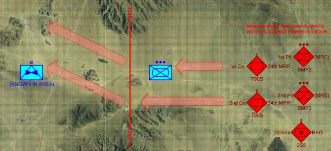
Figure 10: OPFOR Situation.
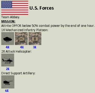
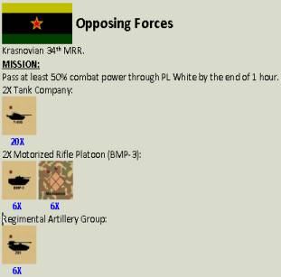
Figure 11: Team Abbey force composition.
17 Future CAPABILITIES
Future work includes the release of map and scenario software design tools. Many of the required tools currently exist in an unreleased state. Using these tools, users will be able to create maps for SRTM90 data, texture overlay from DOQ bitmaps, encode terrain GSs, create and modify standard unit templates, and subsequently create scenario orders of battle and new scenarios. The number of participants per scenario will also be able to be modified using a utility. Also, communication ranges based on radio capability and terrain obstructions will be modeled—if a unit is out of communication it cannot be controlled until communication is reestablished. Currently, the hardware accelerated 3D graphics in the client program rely on Microsoft DirectX APIs. In the future this will be augmented by a hardware accelerated OpenGL implementation in order to expand compatibility to an even wider range of video cards and drivers.
18 Conclusion
More information on the BCTWS is available on the historicalsoftware.com website. There is also a 146 minute video demonstration/tutorial available for download that elaborates in detail on most of the program features. Also, functional versions of the software can be downloaded. An enthusiast forum is linked that lets participants share ideas, find opponents, and make suggestions to the developers. Development on the system is ongoing. Figures 12, 13, and 14 show examples of how the map interface appears. Figure 15 (bottom) shows a directory of the client program main window interface and related information.
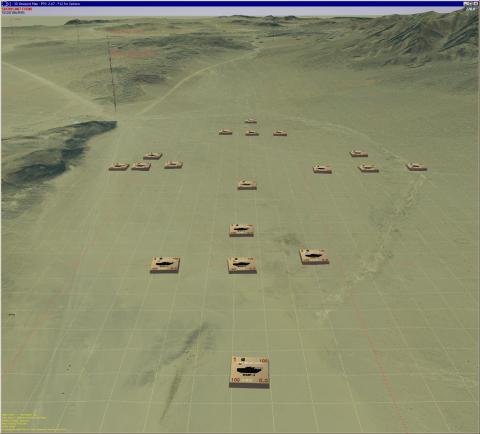
Figure 12: An OPFOR Tank Battalion.
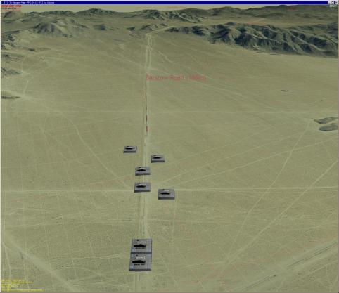
Figure 13: US M1A2 SEP Tank Company.
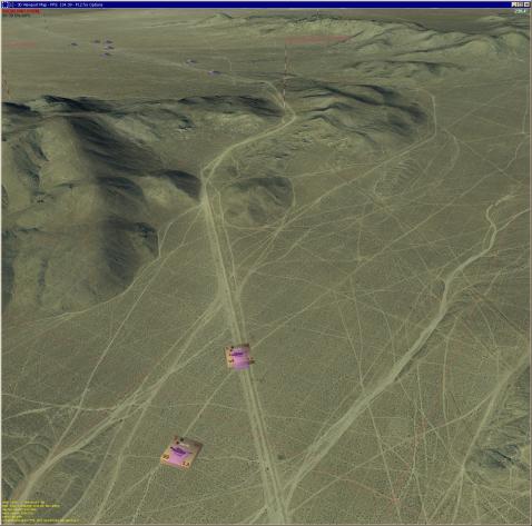
Figure 14: Tanks on the move!
